On 26 August 2026, L&T's Construction and Mining Machinery business signed a partnership with FAYAT's Road Equipment Division, FRED India.
Under the deal, L&T will market BOMAG road milling machines, soil stabilisers, and cement spreaders across India. It also covers sales, after sales support, and spares. (Source: L&T press release, 26 August 2026.)
FAYAT is France's largest independent construction group, active in more than 170 countries. BOMAG is the German brand inside FAYAT's Road Equipment Division.
Abhijit Som, Managing Director of FRED India, and Anil Parab of L&T framed the move around Viksit Bharat 2047 and the country's road building push.
It reads like a machinery story. It is really a story about how one half of construction learned to trust a digital model, and the other half still has not.
What these machines actually do
A modern road mill or soil stabiliser is not just a bigger machine. It executes against a digital surface.
The target grade lives as a 3D model. As the machine works, it reads its own position continuously through GNSS and 3D machine control, and it holds the design surface.
The operator is not chasing string lines and reading a tape. The model is the instruction, and the machine confirms it is meeting that instruction pass after pass.
The model does not sit in an office as a drawing someone consults now and then. It drives the machine, and the machine reports back on whether the ground now matches it.
This is a closed loop. Plan, build, and check become one motion, in real time. When the surface drifts, the machine sees it and corrects before the next pass locks the error in.
Roads closed the loop years ago
Road and earthworks construction has been model-driven for over a decade. GNSS base stations on site, 3D machine control on graders and dozers, and as-built capture on the way out.
The industry moved from build then survey to build to the model and verify as you go.
The payoff is not subtle. Less rework, tighter grade, faster handover, and a record of what was built that matches what was designed.
The model is not a reference document. It is the benchmark the work is measured against, continuously, by the machine doing the work.
| Road construction | Vertical construction |
|---|---|
| The model drives the machine | The model is coordinated in the office |
| Position checked continuously by GNSS | Set out by hand on the floor |
| Verified as the work happens | Verified by tape after the fact, if at all |
| Closed loop | Open loop |
Linear infrastructure had two things going for it. The geometry is open and long, which suits GNSS. The machines were built to take a digital surface as an input.
Put those together and the loop closes on its own. The operator trusts the model because the machine keeps proving the model is being met.
A BIM lead watching a stabiliser hold grade to a model would recognise the idea at once. It is the same idea they apply in the office. The difference is that on the road, the idea reaches the ground.
Buildings never did
Vertical construction has no equivalent. We model to LOD 400. Every duct, every hanger, every penetration is coordinated to fabrication detail. The model is often excellent.
Then it stops at the site boundary.
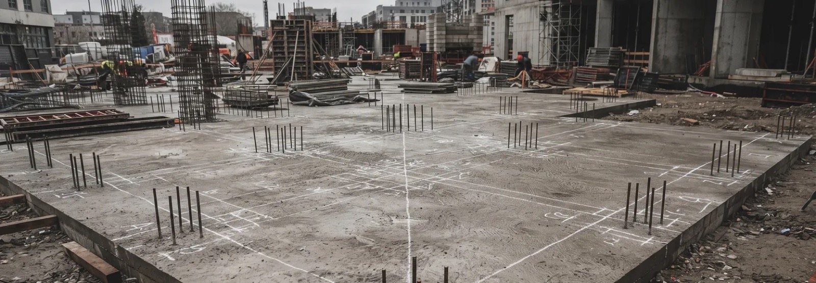
On the floor, the loop breaks. Work is set out by hand. Verification, when it happens at all, is a person with a tape and a printed drawing, checking after the fact.
The model that cost so much to coordinate never checks itself against the concrete.
Part of the reason is physics. GNSS does not reach reliably indoors, between floors, or under a slab. The anchor that road machines lean on is simply not there.
The cost of the open loop is well documented. Navigant Consulting put rework at 5 to 9 percent of contract value in 2012. Much of it traces back to work that did not match the plan rather than to bad engineering.
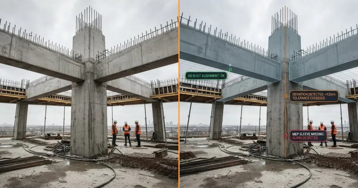
A wall shifts to clear a door. A sleeve is missed in the pour. A duct drops to clear a beam and nobody writes it down.
The ceiling closes. The mismatch surfaces years later, when a facilities team opens it up to reach a valve that is not where the drawing says.
Roads fixed this with GNSS and machine control. Buildings can fix it too, but the anchor has to work inside a structure.
Device tracking and LiDAR give you that anchor. You bring the coordinated model to the site on a tablet, overlay it on the real structure, and read the gap between the two while it is still cheap to close.
FIELD PROOF
On a real slab, DeltaARBIM verified 152 structural elements in place against the model to within 2 cm, before the next trade built on top. That is the confirmed field result, not a projection.
What BIM and VDC leads should take from this
The lesson from the road side is not to buy an AR BIM tool. It is to treat the model as something you verify against on site, not only something you coordinate in the office.
Close the loop. Set out from the model, then confirm what was built matches it before it gets covered.
That single habit is what turned road building from survey after the fact into build to the model.
DeltaARBIM handles the on-site BIM verification half of that loop. Some teams call it BIM validation. It does not author your models, and it does not replace your coordination team.
The gap usually hides above the ceiling. It also shows up differently for every firm on a project. If you want to see it on your own model, book a short demo.
I have spent enough time in models and on slabs to find this split frustrating. The office half of construction is digital and full of capable BIM solutions. The site half is still, too often, a tape measure.
The road industry already crossed that line. Buildings are next, and the anchor is finally there to do it.
References
- L&T press release, 26 August 2026
- EPC World
- Construction Mirror
- Topcon, milling machine guidance and automation
- Leica Geosystems, pavement milling solutions
- Hemisphere GNSS, GNSS-based 3D machine control
- Projul, GPS machine control accuracy, March 2026
- Scotty's Contracting, 3D machine control contractor guide, October 2025